I wanted to cut a decal, and I settled on the symbol for the rebel alliance from Star Wars:
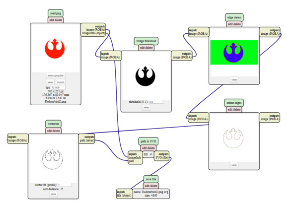
The first thing I did to use our vinyl cutter was to vectorize the image. I found that the algorithm used in mods, has many settings, and I finally got it working. In Mods, all you have to do is load the PNG image and set the "VectorFit" value.
Here are the images starting from the original image, then vector fit of 0.9 , 0.5 , 0.1 . :
This is the final vector file, which was downloaded in SVG format directly from mods.
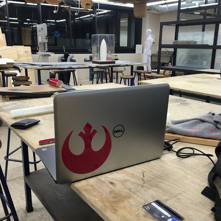
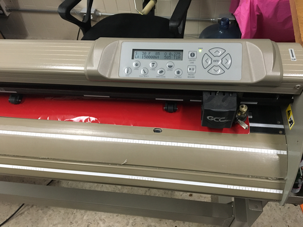
Cutting on the vynil cutter, and pasting the decal on the laptop.
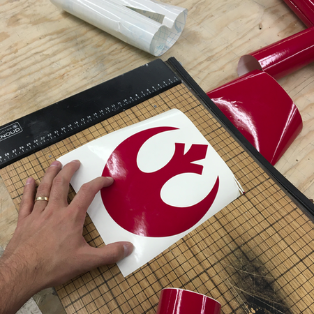
The process of transferring and weeding was easy because the design was pretty simple:
The vynil cutter is pretty straight forward, just make sure that the rollers snap onto the material correctly.
I did the weeding first, I believe that the best practice is to weed once it's on the surface, but I forgot about that.
I didn't have a transfer ply onhand, so I used some wrapping plastic that worked fine, although it was a bit stiff.
pasting the decal on the laptop means taking the transferring medium off, and making sure that no bubbles are left on the vynil.
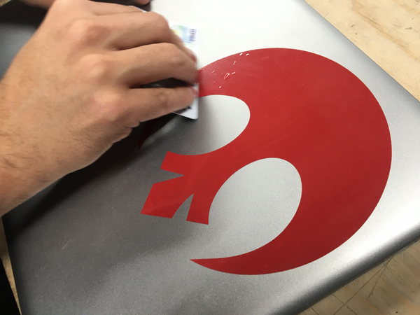
Uh oh... There were some bubbles I had to take out using a credit card.
That was it for the Vynil cutting. It was the first time I did it, and my laptop now looks amazing!!! May the force be with you.
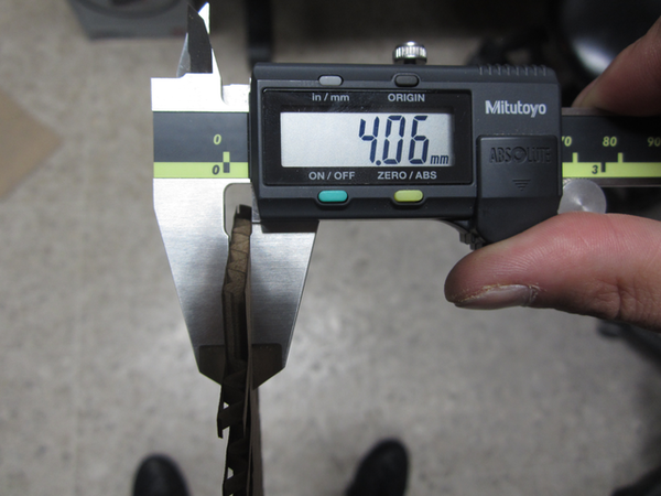
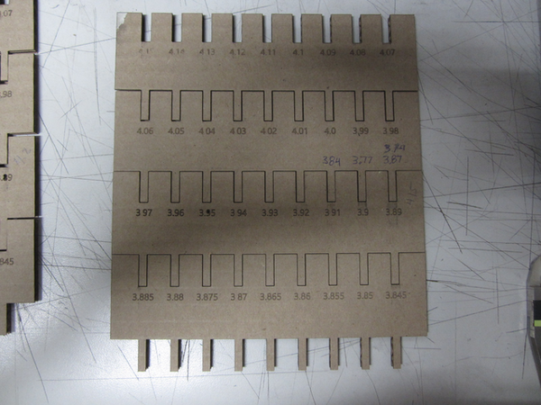
Characterizing the joint clearance
The first thing I did, was measure the cardboard. The caliper gave soemthing around 4.06 mm. To check the joint clearance, I decided to make a parametric model with many notches that prograssively became smaller. I tested each one, and found that 3.85 was the best fit. That would mean that (4-06-3.85)/2=0.105mm is the actual kerf for our laser cutter.
Also, these were the parameters for cutting the cardboard:
Speed: 4.0%
Power: 70%
PPI:400
I didn't use any engraving on this project, but it would have been:
Speed: 70%
Power: 35%
PPI:400
Making the parametric model
After that The parametric model of my pieces was updated to include that information. My pieces were made with the idea of having one piece that can become bigger versions of itself. I made the parametric model in grasshopper:
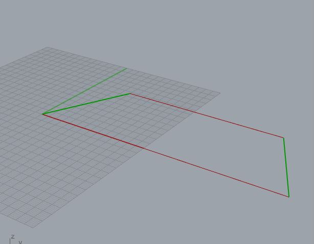
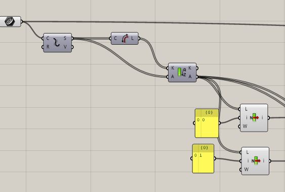
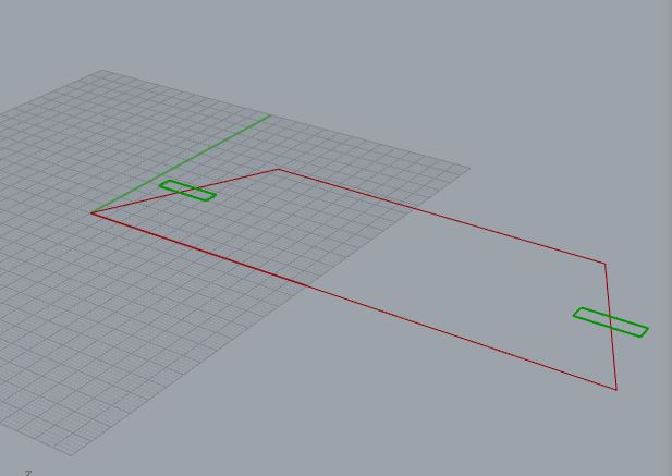
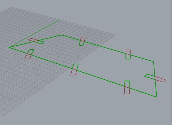
The first step in this parametric model is to start with an appropiate polyline. It's important to note that this weird shape is a trapeze that comes from repeating an equilateral triangle. I use grasshopper to select the shortest sides.
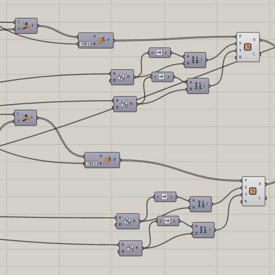
Grasshopper explodes the curve, then queries the resulting list to get the curve lengths and sorts them in ascending order. after that I select the first two curves.
On the selected sides, I draw two rectangles. They come from fist a horizontal frame on the curve, that is rotated exactly 30° or -30° and then I draw the rectangles by getting all the dimmensions rioght on the rectangle domain: depth, width of the kerf.
The rectangle is controlled by a domain that is calculated by dividing desired width and depth.
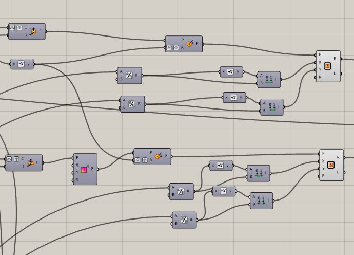
After that I move on to the longer sides. Of these, one is shorter, but uit is shorter exactly the length of the other two sides, so I can divide these rectangles using math.
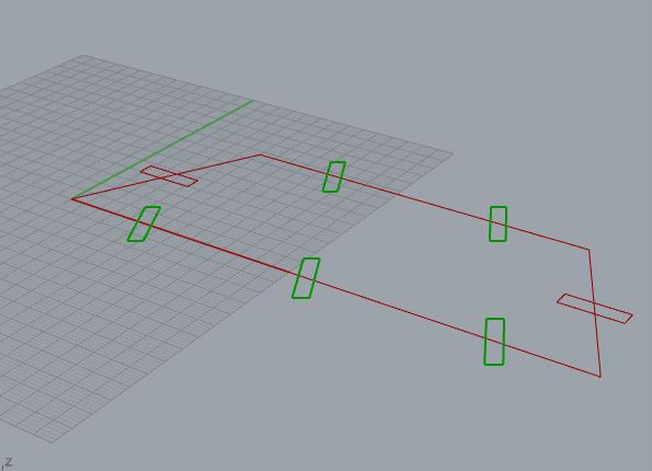
The longer side is divided in 6 equal sides and I draw new rectangles in positions 1, 3 and 5. The shorter side is divided in 4 equal segments and I draw the rectangles in positions 1 and 3.
I basically get the horizontal frame which is the curve's own alignment, and rotate 30° or -30° according to preset parameter.
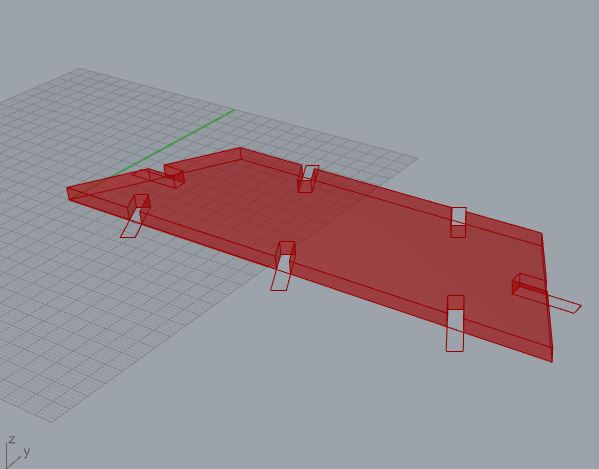
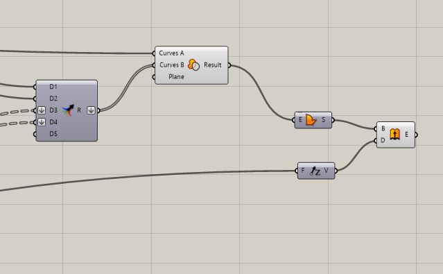
After that I use region difference with the original polyline to extract the geometry of the rectangles from the original outline.
The final step is the extrusion of the shape in order to get the model of the part.
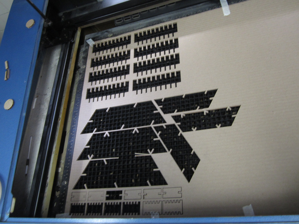
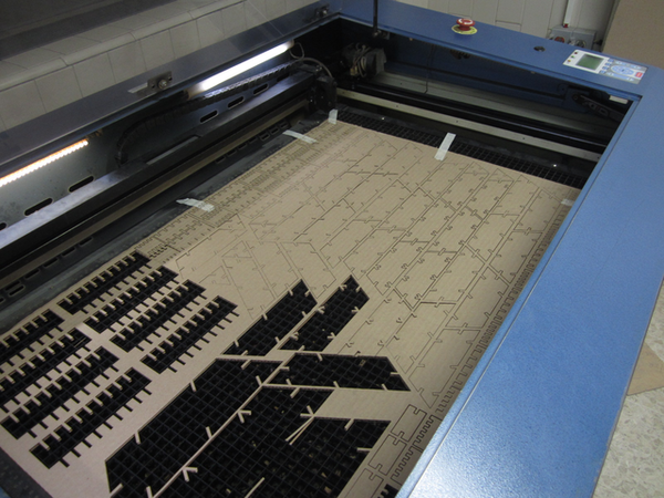
Getting the right size
After that, I made a couple of tests to see which sould be the actual size. I cut these tests and decided on a size for the piece.
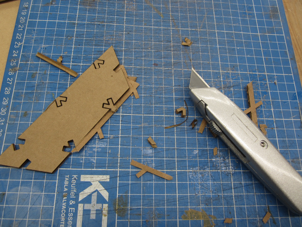
One problem was that the cardboard was a little bit curved, so on a couple of pieces the laser didn't cut all the way through. This happened only to one or two pieces, but I quickly fixed it with the x-acto blade. Building the Model V1
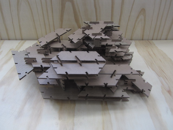
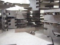
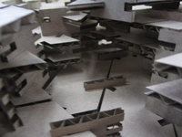
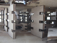
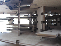
The final model is a somewhat random architectural assembly. I wnted to create something that looked structurally sound and massive, as opposed to just having some flimsy members.
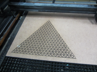
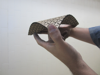
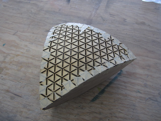
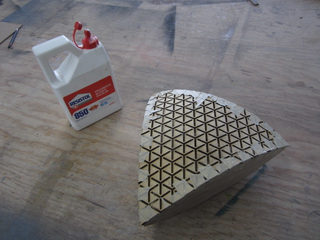
Curved Cutting
Extra credit assignment
I didn't want to miss out on some kerfing and cutting so I came up with this curved piece:
Group Assignment Documentation
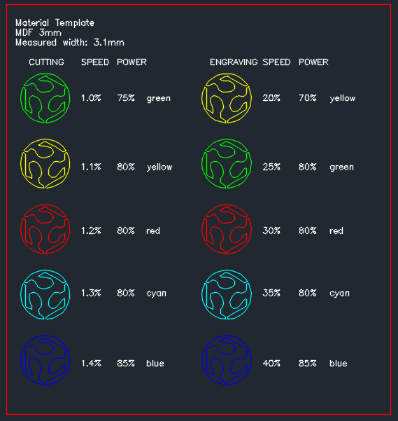
Characterizing 3mm MDF
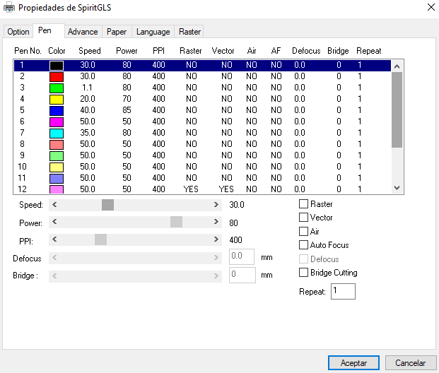
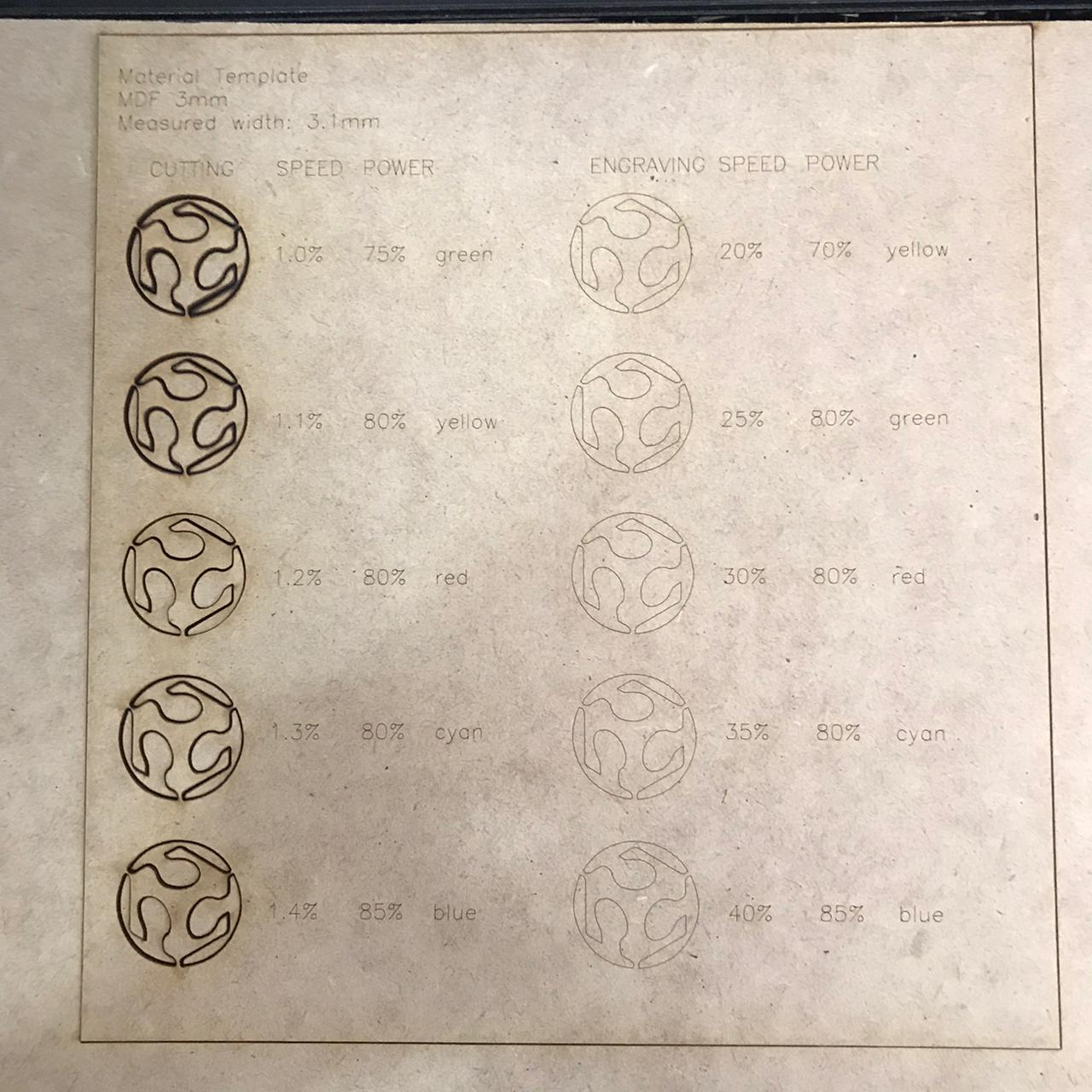
As part of the group assignment, my responsibility was to characterize 3mm MDF on the machine. I made the template and used different settings.
For cutting 3mm MDF the optimum parameters are:


 The vynil cutter is pretty straight forward, just make sure that the rollers snap onto the material correctly.
 I did the weeding first, I believe that the best practice is to weed once it's on the surface, but I forgot about that.
 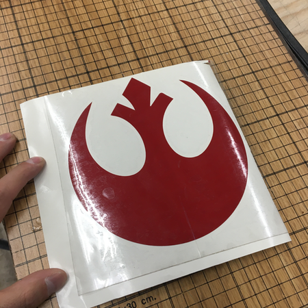 I didn't have a transfer ply onhand, so I used some wrapping plastic that worked fine, although it was a bit stiff.
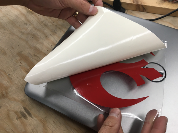
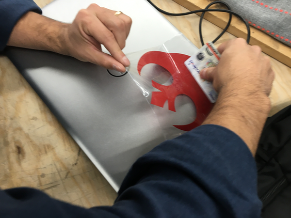 pasting the decal on the laptop means taking the transferring medium off, and making sure that no bubbles are left on the vynil.
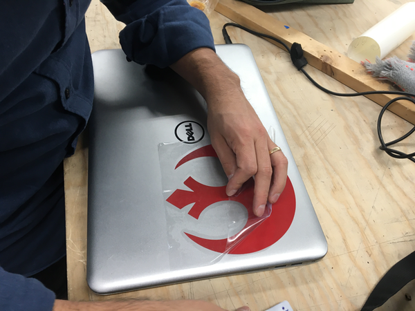
 Uh oh... There were some bubbles I had to take out using a credit card.